Difference between revisions of "Second Life Railroad/SLRR Switch"
m (moved Second Life Railroad/SLRR Switch concept to Second Life Railroad/SLRR Switch: LDPW made a SLRR Switch design that is no longer a concept) |
(Compleet new document based on the LDPW design of the swtich as discussed on 18th august 2010 durning LDPW Railway Brown Bag meeting) |
||
| Line 31: | Line 31: | ||
==Description== | ==Description== | ||
<div style="padding:0.5em"> | <div style="padding:0.5em"> | ||
The following page describes the working and standards used on the LDPW switch. The SLRR switch is part of the greater SLRR rail network and will be implemented over the next months. | |||
</div></div> | </div></div> | ||
| Line 37: | Line 37: | ||
==Background information== | ==Background information== | ||
<div style="padding:0.5em"> | <div style="padding:0.5em"> | ||
On the Northern Continent there are a few sections of railway | On the Northern Continent (Heterocera Atoll) there are a few sections of railway line (see [[Second_Life_Railroad|SLRR Map]] ). Some are under construction and other are in full operation. The LDPW has started work to get the 'Branch lines' and 'Passing tracks' connected to each other. In order to do this a rail switch was designed by {{User2|Sylvan Mole}}. | ||
The basis for the design of the switch was the concept; "The switch should work for the greatest number of existing rolling stock". For that reason the switch is design without active scripts inside the guide rail prims. Most of the parts of the switch are mostly cosmetics. The actual switching is done by changing the (invisible) center guide rail. This is done in such a way that physical trains as well as sensor driven train can use the switch. (see below for more details). | |||
</div></div> | </div></div> | ||
| Line 52: | Line 47: | ||
==Drawing== | ==Drawing== | ||
<div style="padding:0.5em"> | <div style="padding:0.5em"> | ||
[[File:Points_expl.png|600px|center| | ====Diagram of Switch parts==== | ||
* Guide rail | |||
[[File:Points_expl.png|600px|center|Drawing semi automated switch]] | |||
* Guide rail (normally invisible but as example colored in) | |||
*# white normal [[Second_Life_Railroad/SLRR_standards#Standards|Guide rail]] | *# white normal [[Second_Life_Railroad/SLRR_standards#Standards|Guide rail]] | ||
*# green normal Guide rail on the switch named "Guide" | *# green normal Guide rail on the switch named "'''Guide'''" made '''not phantom''', in other words, made solid | ||
*# red switched off Guide rail and renamed " | *# red switched off Guide rail and renamed "'''Alternate Guide'''" and made '''phantom''' | ||
* | * Switch stand | ||
* | * Sensors | ||
*# A for trains going down the main line | *# A for trains going down the main line, from the merge side toward the heading of the switch | ||
*# B for trains going down the branch line toward the | *# B for trains going down the branch line, from the merge side toward the heading of the switch | ||
* | * Dwarf Signal Lights | ||
====Switch stand signaling diagram==== | |||
[[File:SLRR_Switch_Signaling_1024.png|600px|center|Drawing of Swtich stand signaling]] | |||
</div></div> | </div></div> | ||
| Line 69: | Line 71: | ||
==System description== | ==System description== | ||
<div style="padding:0.5em"> | <div style="padding:0.5em"> | ||
===Basics=== | ===Basics=== | ||
*A Guide rail in use (direction of travel, depicted in green) | *A Guide rail in use (direction of travel, depicted in green) | ||
prim attributes | prim attributes | ||
| Line 80: | Line 81: | ||
- NOT phantom | - NOT phantom | ||
- Material: Glass | - Material: Glass | ||
- Texture: Transparent | - Texture: Transparent | ||
*A Guide rail not in use (switched off, depicted in red) | *A Guide rail not in use (switched off, depicted in red) | ||
prim attributes | prim attributes | ||
- prim name: ' | - prim name: 'Alternate Guide' | ||
- phantom | - phantom | ||
- Material: Glass | - Material: Glass | ||
- Texture: Transparent | - Texture: Transparent | ||
* | *Switch Stand Signal rotates 90deg. to reveal appropriate signal. It houses the main scripts that talk to the Guide rail sections as well as the train sensors A and B. | ||
* | *Sensors look straight up for 4 meters, sensing ACTIVE unflagged, with an arc as wide as the [[Second_Life_Railroad/SLRR_standards#SLRR_track_standards|Loading Gauge]]. If a train is detected it will automatically switch to the appropriate setting. However, If you go too fast into a merge they may miss detecting the train. | ||
*Dwarf Signal Lights on the Merge side of the switch display a Green or Red light. A green Dwarf Signal on the side of the merge you are on, means the switch is set correctly. A red Dwarf Signal on the side of the merge you are on, mean switch set incorrectly. Going on past a red light may cause trains to derail. | |||
===Touch Start=== | |||
To provide touch support to each switch, there is a larger invisible cube placed over each switch (see drawing: purple box over the switch).<BR> | |||
Simply hover your mouse over the area and click. These are very large and not part of the linkset to avoid LOD and distance rendering issues. | |||
===System messaging=== | |||
*All switch systems message on a unique channel published in the Object Description of the switch stand linkset. | |||
*All switch systems listen for the message "main" OR(not and) "branch" on appropriate channel. | |||
*All switch systems llShout (100 meter) "main" or "branch" on the same channel once switch has completed changes. | |||
This allows signal changes up to 100 meters further up and down line. Including communication between LDPW construct and private installations. | |||
===Switch stand Prim/linkset parameters and changes and data string=== | |||
Object Description of the switch stand root holds a data string. This data will make it possible for train builders to semi-automate trains / train routes, as well as get enough information to message switches appropriately. i.e. control switches by sending messages 'main' or 'branch' to it.<BR> | |||
String format -Identifier~Status~Heading Name~Mainline Name~Branch Name~messaging channel<BR> | |||
Format uses ~ to separate fields of data and "." to designate hierarchies within fields | |||
Notation example: | |||
SimName.x.y.z~Main~Heading~Mainline~branch~channel | |||
Live example: | |||
Tuliptree.30.42.30~Branch~Calleta Station~TulipTree Station~VRC Yard~133 | |||
* | explanation of the live example: | ||
** | * The switch is located in Tuliptree/30/42/30 | ||
* | * It is currently set to the branch | ||
* | * The heading side goes to Calleta Station | ||
* The main side goes to Tuliptree Station | |||
* The branch side goes to VRC Yard | |||
* It listens and talks on channel 133 | |||
So in this example the switch is set to the branch line that links the VRC-Yard in Tuliptree to the Calleta Station. | |||
* | If the switch was turned the other way (to mainline going straight ahead) it would read: | ||
Tuliptree.30.42.30~Main~Calleta Station~TulipTree Station~VRC Yard~133 | |||
The data string changes only the Status field during normal operation. The 'Status' field will display "Main" or "Branch" for train builders/scripters to sense and react. | |||
===Sensors. and mainline resets.=== | |||
*Each switch installed on a mainline will reset to the mainline position 2.5 minutes after it is put in the branch position. | |||
*On the merge side of each switch are two sensors, One for each side of the merge. These effectively "Spring" the switch correctly for traffic heading into the merge. When tripped they messages the switch and set it to the correct position. | |||
*The sensor scripts are placed in a prim 1.0x0.5x0.5 meter and positioned on/inside the guide rail. | |||
*These sensors look straight up for 4 meters, sensing ACTIVE unflagged, with an arc as wide as the Loading Gauge. However, If you go too fast into a merge they may miss detecting the train. | |||
</div></div> | </div></div> | ||
| Line 114: | Line 145: | ||
==Source== | ==Source== | ||
<div style="padding:0.5em"> | <div style="padding:0.5em"> | ||
The above information was | The above information was provided by LDPW {{User2|Sylvan Mole}} and edited for the wiki by {{User2|Stryker Jenkins}}. | ||
</div></div> | </div></div> | ||
Revision as of 07:24, 29 August 2010
| Help Portal: |
Avatar | Bug Fixes | Communication | Community | Glossary | Land & Sim | Multimedia | Navigation | Object | Video Tutorials | Viewer | Wiki | Misc |
| Note! | |
|
As with all wiki.secondlife pages that are not LL Official pages, this article is open to edit as and when a resident feels it is appropriate (see Editing Guidelines). If however you simply wish to ask or make a suggestion about or discuss the railroad or the content of this article, please use the Talk page. The talk page is also where any disputes over proposed page content should be discussed. This Wiki (being a document of an ever changing world) is constantly in need of updating and improvement. If you are aware of information this article should have added/changed please go ahead and do so. If you do not feel confident about editing make the suggestion on the talk page and another contributor may be able to assist. |
Description
The following page describes the working and standards used on the LDPW switch. The SLRR switch is part of the greater SLRR rail network and will be implemented over the next months.
Background information
On the Northern Continent (Heterocera Atoll) there are a few sections of railway line (see SLRR Map ). Some are under construction and other are in full operation. The LDPW has started work to get the 'Branch lines' and 'Passing tracks' connected to each other. In order to do this a rail switch was designed by Sylvan Mole.
The basis for the design of the switch was the concept; "The switch should work for the greatest number of existing rolling stock". For that reason the switch is design without active scripts inside the guide rail prims. Most of the parts of the switch are mostly cosmetics. The actual switching is done by changing the (invisible) center guide rail. This is done in such a way that physical trains as well as sensor driven train can use the switch. (see below for more details).
Drawing
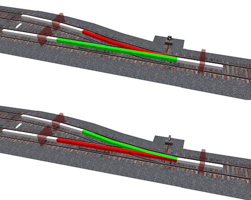
Diagram of Switch parts
- Guide rail (normally invisible but as example colored in)
- white normal Guide rail
- green normal Guide rail on the switch named "Guide" made not phantom, in other words, made solid
- red switched off Guide rail and renamed "Alternate Guide" and made phantom
- Switch stand
- Sensors
- A for trains going down the main line, from the merge side toward the heading of the switch
- B for trains going down the branch line, from the merge side toward the heading of the switch
- Dwarf Signal Lights
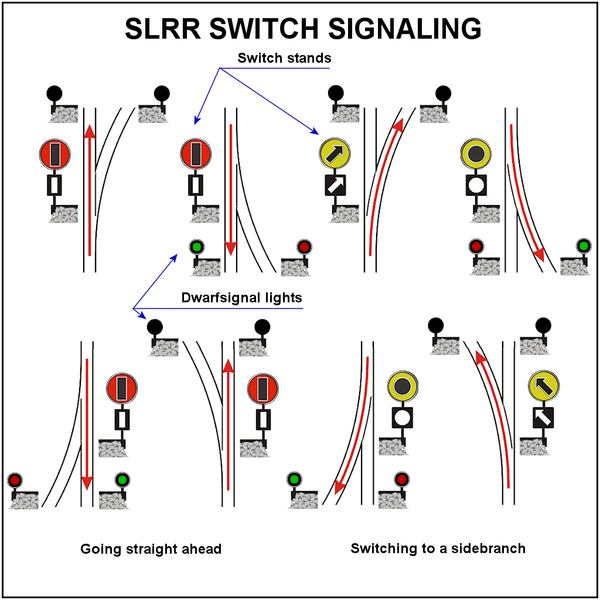
Switch stand signaling diagram
System description
Basics
- A Guide rail in use (direction of travel, depicted in green)
prim attributes
- prim name: 'Guide'
- NOT phantom
- Material: Glass
- Texture: Transparent
- A Guide rail not in use (switched off, depicted in red)
prim attributes
- prim name: 'Alternate Guide'
- phantom
- Material: Glass
- Texture: Transparent
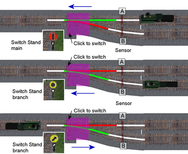
- Switch Stand Signal rotates 90deg. to reveal appropriate signal. It houses the main scripts that talk to the Guide rail sections as well as the train sensors A and B.
- Sensors look straight up for 4 meters, sensing ACTIVE unflagged, with an arc as wide as the Loading Gauge. If a train is detected it will automatically switch to the appropriate setting. However, If you go too fast into a merge they may miss detecting the train.
- Dwarf Signal Lights on the Merge side of the switch display a Green or Red light. A green Dwarf Signal on the side of the merge you are on, means the switch is set correctly. A red Dwarf Signal on the side of the merge you are on, mean switch set incorrectly. Going on past a red light may cause trains to derail.
Touch Start
To provide touch support to each switch, there is a larger invisible cube placed over each switch (see drawing: purple box over the switch).
Simply hover your mouse over the area and click. These are very large and not part of the linkset to avoid LOD and distance rendering issues.
System messaging
*All switch systems message on a unique channel published in the Object Description of the switch stand linkset.
*All switch systems listen for the message "main" OR(not and) "branch" on appropriate channel.
*All switch systems llShout (100 meter) "main" or "branch" on the same channel once switch has completed changes.
This allows signal changes up to 100 meters further up and down line. Including communication between LDPW construct and private installations.
Switch stand Prim/linkset parameters and changes and data string
Object Description of the switch stand root holds a data string. This data will make it possible for train builders to semi-automate trains / train routes, as well as get enough information to message switches appropriately. i.e. control switches by sending messages 'main' or 'branch' to it.
String format -Identifier~Status~Heading Name~Mainline Name~Branch Name~messaging channel
Format uses ~ to separate fields of data and "." to designate hierarchies within fields
Notation example:
SimName.x.y.z~Main~Heading~Mainline~branch~channel
Live example:
Tuliptree.30.42.30~Branch~Calleta Station~TulipTree Station~VRC Yard~133
explanation of the live example:
- The switch is located in Tuliptree/30/42/30
- It is currently set to the branch
- The heading side goes to Calleta Station
- The main side goes to Tuliptree Station
- The branch side goes to VRC Yard
- It listens and talks on channel 133
So in this example the switch is set to the branch line that links the VRC-Yard in Tuliptree to the Calleta Station.
If the switch was turned the other way (to mainline going straight ahead) it would read:
Tuliptree.30.42.30~Main~Calleta Station~TulipTree Station~VRC Yard~133
The data string changes only the Status field during normal operation. The 'Status' field will display "Main" or "Branch" for train builders/scripters to sense and react.
Sensors. and mainline resets.
- Each switch installed on a mainline will reset to the mainline position 2.5 minutes after it is put in the branch position.
- On the merge side of each switch are two sensors, One for each side of the merge. These effectively "Spring" the switch correctly for traffic heading into the merge. When tripped they messages the switch and set it to the correct position.
- The sensor scripts are placed in a prim 1.0x0.5x0.5 meter and positioned on/inside the guide rail.
- These sensors look straight up for 4 meters, sensing ACTIVE unflagged, with an arc as wide as the Loading Gauge. However, If you go too fast into a merge they may miss detecting the train.
Source
The above information was provided by LDPW Sylvan Mole and edited for the wiki by Stryker Jenkins.


