Difference between revisions of "Mesh and LOD"
| Line 78: | Line 78: | ||
==Physics== | ==Physics== | ||
Second Life supports custom physics shapes | Second Life supports custom physics shapes, both uploaded with a mesh object or uploaded independently. This allows for the creation of a visually complex object that has a low physics weight. | ||
=== | ===Havok Physics tips and oversimplifications=== | ||
[https://wiki.secondlife.com/wiki/Physics_engine Havok] LOVES cubes, and here is why: Havok is optimized to process cubes nearly instantaneously. Conversely, when Havok encounters an object more complex than a cube(even a hollow or cut cube) it then has to count ''every single triangle'' on that object and ponder what to do with each one. So keep those physics shapes as simple as possible! | |||
===Physics shapes and how they relate to mesh uploads and LOD=== | ===Physics shapes and how they relate to mesh uploads and LOD=== | ||
Revision as of 09:57, 21 November 2012
Mesh basics
A mesh is of a collection of vertices, edges, and faces that define a 3D shape.
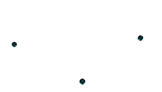 The basic element of a mesh is a vertex. Vertices represent points in space.
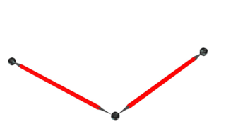 Edges are lines that connect two vertices.
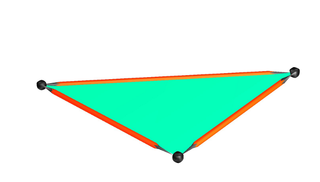 A face is a triangle composed of three vertices connected by edges.
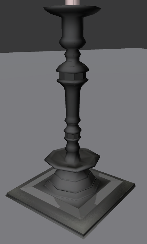
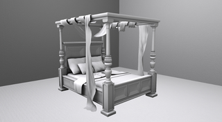 Together, they can combine to make models that look like this!
File Format
Second Life can import meshes in the COLLADA 1.4.1 (.dae) file format. COLLADA is a powerful open standard format consisting of human-readable XML. Although Second Life uses COLLADA for importing mesh data, it internally uses a custom format for uploading, storage, and streaming of mesh content.
| Note: While the COLLADA spec supports everything from polygons to nurbs, the Second Life mesh importer only imports polygonal data. This means that you must convert your models to meshes before exporting to a COLLADA file. |
More than you'll ever need to know about COLLADA:
Software
There are many applications that can create mesh and export to COLLADA. Here is a short list of some popular tools:
- Maya
- 3dsMax Many other Autodesk tools can also export to COLLADA.
- Blender Additional Second Life Mesh Blender specific tutorials here: http://blog.machinimatrix.org/ and http://cgcookie.com
- Wings 3D No UV mapping tool.
- Daz Studio
Many other software packages can create mesh, though some may require minor settings adjustments or even external programs to generate .dae files.
Here is a more extensive list on the Second Life Wiki: Mesh/Tools
Here are some examples of files in COLLADA .dae file format. Mesh/Sample_Content
Level Of Detail
Level of Detail (LOD) is the mechanism by which Second Life lowers an object's visual detail by increments as the camera gets further away. When uploading a mesh model, we have complete control over the amount of detail at each level.
- The uploader supports four levels of detail.
- The uploader automatically generates lower LODs suitable for preview or rough import. You can achieve smoother transitions between levels by creating your own lower LOD models.
- LOD culling (the viewing distance at which the detail levels change) is affected by an object's scale. A large object shows a higher LOD than a smaller object at the same distance. Remember this when creating your LOD models and when uploading.
- The uploader allows the same file to be used in multiple LOD level slots. This is useful for ensuring detail on smaller objects but use it wisely; using a highly detailed model in all slots can adversely affect the model's land impact and rendering performance.
- Make sure the bounding boxes of all the LOD models are identical in size. This prevents the object from changing its scale as it transitions through the LOD levels. Most modeling applications offer ways to view the bounding box of multiple objects at the same time.
- Each LOD model must retain all the materials of the highest detailed model. If your model has 8 materials, so must all your LOD models. Ignoring this will result in unpredictable texture location changes. Ignoring the materials requirement won't stop the uploader. If you have a model that is displaying textures improperly, look closely at the materials in your LOD files.
- A general guideline for creating LOD models is to reduce the polygon count by 50%-75% at each level. For example: If the most detailed model is 400 polygons, the next level should be no higher than 200 polygons. The next level should be no higher than 100, and the lowest should be near or below 50 polygons.
Uploading a mesh model step by step on the Second Life Knowledge Base: Uploading a mesh model
Brief Uploader LOD section walk through
Uploader Generated LODs
- Choose Build > Upload > Model... from the top menu bar.
- In the High file slot click Browse, then select the .dae file on your computer and click Open.
- Click on the Medium level slot to highlight that level. Highlighting any level displays that level's model in the Preview pane. Use the up and down arrows on each level to raise or lower the triangle count until satisfied with the transition between the LODs.
- Click Calculate weights & fee and see if you like the Land Impact count, but don't upload yet! We still need to adjust the model's physics properties.
For full details on Triangle Limit and Error Threshold, see Upload Model UI reference.
User created LOD files
- Choose Build > Upload > Model... from the top menu bar.
- In the High LOD slot load the highest detailed model as described above.
- In the Medium slot load the second highest LOD model.
- In the Low file slot load the second to lowest LOD model
- In the Lowest slot load the lowest LOD model.
- Click Calculate weights & fee and see if you like the Land Impact count, but don't upload yet! We still need to adjust the model's physics properties.
Physics
Second Life supports custom physics shapes, both uploaded with a mesh object or uploaded independently. This allows for the creation of a visually complex object that has a low physics weight.
Havok Physics tips and oversimplifications
Havok LOVES cubes, and here is why: Havok is optimized to process cubes nearly instantaneously. Conversely, when Havok encounters an object more complex than a cube(even a hollow or cut cube) it then has to count every single triangle on that object and ponder what to do with each one. So keep those physics shapes as simple as possible!
Physics shapes and how they relate to mesh uploads and LOD
- Creating your own physics shapes in a modeling application is easy.
- Keep the poly count extremely low.
- Make sure the physics shape model fills the bounding box of your model and LODs, or it will not line up with your visual geometry.
- Export using a .dae COLLADA file.
The physics tab of the uploader step by step. [1]
This tab allows nearly infinite flexibility. Here is a quick description of the uploader physics tab. This is redundant but is needed to illustrate the importance and usefulness of the Analyze button.
Step 1: Level of Detail
- You can assign any of your LOD levels as the physics shape.
- Or insert a new file for the physics shape.
- Or generate the physics shape right there in the uploader.
Step 2: Analyze IMPORTANT
- A mesh physics shape uploaded without using the Analyze button will result in the faces being double sided inworld. For instance: a single plane will upload as a double sided wall. A cube will upload as a hollow box. This is useful for creating simple shapes, but also risky as it can create areas that will trap avatars and other physical objects.
- Pressing the Analyze button changes all those double sided faces into single sided faces with respect to the normal direction. It also creates a physics shape that acts as a volume. Much like a prim, an Avatar or physical object interpolated with an Analyzed physics shape is neatly pushed out of the volume by Havok.
Step 3: Simplify
- From here you can simplify.
- close holes in more complex shapes. This is useful when using an LOD level for the physics shape.
The goal should always be a the simplest physics shape possible. Using the uploader tools here to keep the geometry and physics count as low as possible.
UV mapping
Anyone who has used the Build Tools inside of Second Life already understands UV mapping, but perhaps under different terminology. UV mapping is simply setting texture repeats(U and V) and offsets. If you look closely at the Build Tools Texture tab you'll see that U and V are used for the texture offset values already. Lean on that familiarity and this concept will come more easily. (world map image illustrating unwrapped earth)
General UV mapping techniques
Standard UV mapping
The most common UV map technique divides the mesh surface into neatly flattened sections. Most 3D modeling software packages have this functionality built in. The result is familiar to us and looks like this: (image of SL face UV map)
UV mapping this way has advantages and disadvantages.
- The shapes created usingthis UV mapping technique makes it easier to visualize how the texture will apply inworld, which makes modifying and drawing on the texture easier.
- Most 3D modeling software packages can be used to generate beautiful textures using this mapping technique(in conjunction with Projection mapping, scene lighting, etc.).
- The disadvantages come in to play with larger or very complex objects. One simple runs out of pixels(or texture space) if trying to flatten a complex object onto one UV map. Large objects often need a seamless repeatable texture.
(image of theater UV with zanny blurry wallpaper.)
Projection UV mapping
Projection UV mapping is much like applying textures to a prim object inworld, the goal of UV mapping this way is to scale, rotate, and offset a diffuse texture so the object wears it perfectly.
- The advantage of mapping this way for Second Life is versatility. A house UV mapped this way can wear any number of standard wall, roof, or trim textures.
- The texture can be repeat and offset.
- The texture can be animated.
- disadvantages:
- potential for texture size overuse inworld.
- Models uploaded with projection UV maps can not take advantage of modeling softwares texture baking capability.
(image of wall wearing obvious square textures)
Baking textures
An advanced feature of most modeling software packages uses both the Standard UV map and the Projection maps to render an image is sometimes referred to as Baking a texture. The goal is to use all the texture information stored in the Projection maps to create an image that fits the Standard UV map. This render can influenced by any lighting or other objects in the scene.
Texture Faces
- Second Life's COLLADA mesh uploader supports up to 8 separate texture faces.
- Each LOD model must all have the same number of Texture faces.
- All the separate faces need to use the same UV map.
- Each modeling software handles this slightly differently. Assigning different areas to different materials archives separate Texture faces on an uploaded Mesh in some modelers, and assigning areas to separate textures achieves this in others. Application specific information [2]
Normals
Normal is an adjective that describes something that is perpendicular to a plane. [3] For the scope of this article, normal describes the direction a face is pointing. Most 3d renderers, the Second Life Viewer included, smartly render only one side of a face. This saves cycles but assumes model is Manifold (enclosed in a way that won't encourage views inline with the normal, or are double sided where needed)
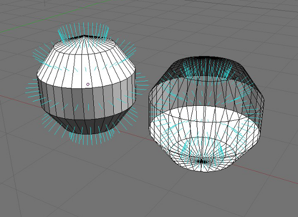 Two spheres. Left: Normals pointing out, Right: Normals pointing in.
Smooth Normals
In the case of a round or curved multiple face surface, a Normal average can be used; which allows an inexpensive surface smoothing. Commonly known as Smooth Normals or Smooth shading, it is an invaluable tool when creating low poly Second Life content. Smooth Normals allow fewer faces to achieve a visually smooth surface. Far far fewer faces. For example, a five sided cylinder with smooth normals can appear completely round in Second Life. In some cases, a three sided cylinder will appear perfectly round.
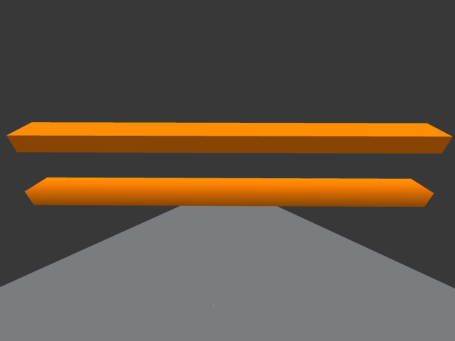 Two 5 sided cylinders. Top: Solid Normals. Bottom: Smooth normals.
Note where both cylinders intersect the walls, they show the profile of the actual geometry.
Applying Smooth Normals to some areas and not to others is another useful for adding detail or highlighting edges.
Low poly modeling
We are not making the next Avatar movie, we are streaming triangles and data near the speed of light. Make sure each and every poly and bit counts. There are many low poly modeling techniques and software specific tutorials and tools available around the web. [4]
The goal should always be to save every triangle everywhere you can on the model you plan to upload.
- Ensure that any flat surface uses the least amount of faces as possible.
- Use Smooth Normals to fake smooth curved surfaces.
- Use a low poly rendering tricks to bake detailed textures.
Low Poly Texture baking tricks
The idea is to create a very highly detailed model and use it to render gorgeous textures on to a very simple low poly Second Life friendly version. Making the name low poly modeling slightly deceptive. As you will most likely model and render a very high poly scene. But, the result is a very efficient model with very detailed textures, well poised for incoming Normal and Specular maps.
Most modeling software packages have features built in to facilitate this technique. Look up your favorites', it will be time very well spent.
Best practices hit list
- Low poly count.
- Smart UV mapping for efficient texture use and size.
- Smart LOD settings and files.
- Smart appropriately Analyzed simple physic shapes.
